Chapter 3: Lines and Angles
Lesson 1: Number Operations and Equality
Lesson Outline
Terms: Axiom, equal.
Properties of equality: Reflexive, substitution, addition, subtraction, multiplication, division.
Transparencies
- 3-1-1 Page from Italian geometry book
- 3-1-2 Some properties of numbers
- 3-1-3 Properties of equality applied to a geometric figure
- 3-1-4 Italian proof
- 3-1-5 Binomial square (Set II, Exs. 25-30)
- 3-1-6 Chinese proof (Set II, Exs. 31-35)
Introduction
The lessons in Chapter 2 ended with one on some famous theorems of geometry. Each of these theorems included information that can be stated in the form of an equation: c² = a² + b², ∠1 + ∠2 + ∠3 = 180°, C = πd, A = πr². The page from the Italian geometry book reproduced on Transparency 3-1-1 illustrates the fact that equations are also used in writ-
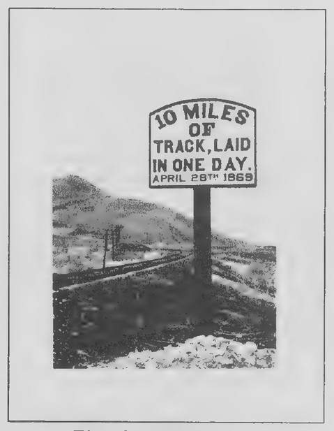 Transparency 3-2-1: Transcontinental railroad sign
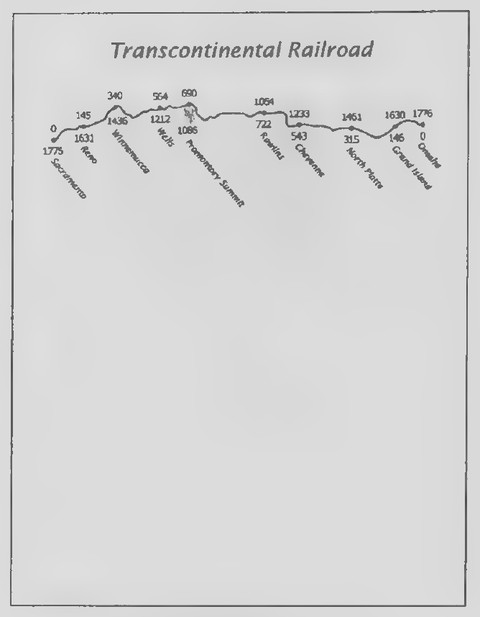 Transparency 3-2-2: Transcontinental railroad map
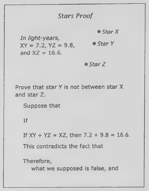 Transparency 3-2-3: Stars proof (Set II, Ex. 45)
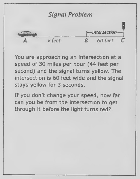 Transparency 3-2-4: Signal problem (Set II, Ex. 46)
ing geometric proofs. (Observe also that there are two references to “il teorema di Pitagora” on this page.) In this lesson, we consider some of the properties of numbers and equations and add them to our logical system. Transparencies 3-1-2 and 3-1-3 are for possible use in developing the lesson as in the text. In using Transparency 3-1-3, keep the statements beginning with ∠A + ∠B + ∠C = 180° covered until your students have had a chance to try to figure out the measure of ∠A. Then reveal the lines of the proof one at a time so that your students can anticipate the steps, as well as giving the reasons. If your students are up to it, you might have them take a further look at some of the proof on the page from the Italian geometry book. (Although it is a development of the Law of Cosines, I suggest that you not mention this fact to your students at this point.) Transparency 3-1-4 can be used for this purpose. Again, uncover the steps as your students consider how they are explained.
Lesson 2: The Ruler and Distance
Lesson Outline
Terms: Ruler, coordinate, distance, between (points).
Postulate 3. The Ruler Postulate: The points on a line can be numbered so that positive number differences measure distances.
Definition: Betweenness of points.
Theorem 1. The Betweenness of Points Theorem. If A-B-C, then AB + BC = AC.
Transparencies
- 3-2-1 Transcontinental railroad sign
- 3-2-2 Transcontinental railroad map
- 3-2-3 Stars proof (Set II, Ex. 45)
- 3-2-4 Signal problem (Set II, Ex. 46)
Introduction
Show Transparency 3-2-1. Although the date on this sign is April 28, 1869, it was an event 2 weeks later that became famous in American history. Do you know what the event was? (The transcontinental railroad was completed on May 10.) Before the completion of this railroad, it took at least 4 months to travel across the United States. Afterward, the trip could be made in just 1 week.
Hand out duplicated copies of Transparency 3-2-2 to your students. Before 1865, railroad tracks had been built from the east coast as far west as Omaha,
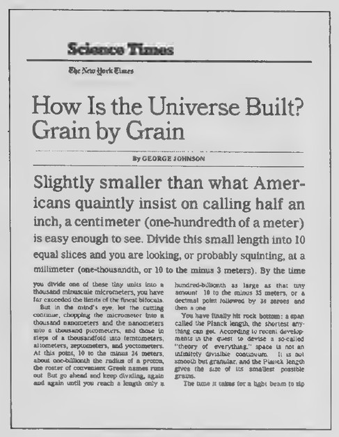 Transparency 3-3-1: How is the universe built?
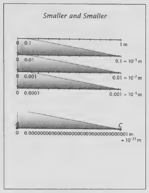 Transparency 3-3-2: Smaller and smaller
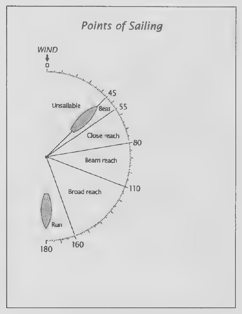 Transparency 3-3-3: Points of sailing
Nebraska. In that year, Union Pacific began laying tracks westward at the same time that Central Pacific was laying tracks eastward from Sacramento. It was Central Pacific that managed to put down 10 miles of tracks in just 1 day just before the two tracks met at Promontory Summit just north of the Great Salt Lake. Two sets of numbers appear on the map on Transparency 3-2-2. What do you suppose they represent? (The distances in miles of the indicated points along the railroad from Sacramento and from Omaha.) How many miles of track did Central Pacific lay from Sacramento to Promontory Summit? (690.) How many miles of track did Union Pacific lay from Omaha to Promontory Summit? (1,086.) How many miles of track connected Reno to Cheyenne? (1,088.) Explain that the two sets of numbers are two coordinate systems. The question about the distance from Reno to Cheyenne reveals that the distance between two points can be found as the positive difference between their coordinates. Further examples from the railroad map can be used to develop the rest of the lesson, including the Ruler Postulate and the ideas concerning betweenness of points. Some students may enjoy learning more about the construction of the transcontinental railroad from the Web site, www.pbs.org/wgbh/ amex/tcrr/sfeature/sf_map.html, which also features an attractive interactive map.
Lesson 3: The Protractor and Angle Measure
Lesson Outline
Terms: Protractor, degree, rotation of rays, half-
rotation of rays, coordinate, measure of angle,
acute, right, obtuse, straight, between (rays). Postulate 4. The Protractor Postulate: The rays ina
half-rotation can be numbered from 0 to 180
so that number differences measure angles. Definition: Betweenness of rays. Theorem 2: The Betweenness of Rays Theorem.
If OA-OB-OC, then ∠AOB + ∠BOC = ∠AOC.
Transparencies
- 3-3-1 How is the universe built?
- 3-3-2 Smaller and smaller
- 3-3-3 Points of sailing
- 3-3-4 Betweenness of Rays Theorem (Set II, Ex. 54)
Review On Transparency 3-3-1 is the beginning of an article from the New York Times (December 7, 1999), about the structure of the universe. It concerns a property of physical space that seems almost impossible to believe because it is so contrary to our intuition. The Ruler Postulate is based on thinking of a ruler as an infinite number line. The points on the line are numbered so that to every point there corresponds exactly one real number called its coordinate and to every real number there corresponds exactly one point. Show Transparency 3-3-2. The figure at the top illustrates the division of a length of 1 meter into 10 equal parts called decimeters (idm=01 m= 10-1 m. The second figure shows the division of 1 decimeter into 10 equal centimeters (1 cm = 0.01 m = 10 m). The third figure shows 1 centimeter divided into 10 equal millimeters, the smallest length that you see marked on a ruler (1 mm = 0.001 m = 10° m). If we imagine continuing this process, we even-
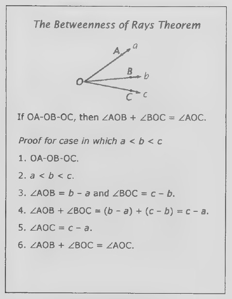 Transparency 3-3-4: Betweenness of Rays Theorem (Set II, Ex. 54)
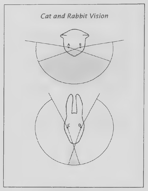 Transparency 3-4-1: Cat and rabbit vision
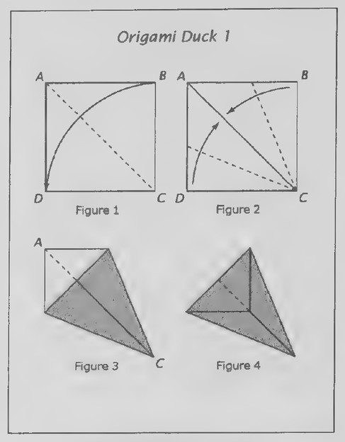 Transparency 3-4-2: Origami duck 1
tually get to a length of 10-* m, and here is the surprise. As the Times article puts it: “You have finally reached rock bottom: a span called the Planck length, the shortest anything can get. According to recent developments in the quest to devise a socalled ‘theory of everything,’ space is not an infinitely indivisible continuum. It is not smooth but granular, and the Planck length gives the size of its smallest possible grains.”
It seems natural to be able to choose points between the points A and C that mark the endpoints of the Planck length. Just choose any number less than 10° and let it be the coordinate of the point. By our definition of betweenness of points, if the coordinate of the point, B, is n and 0 <n < 10°35, then A-B-C. The Ruler Postulate treats geometric “lines” as being “continuous,” meaning that they can be subdivided indefinitely. Physical “lines,” on the other hand, do not seem to be continuous in that they cannot be subdivided indefinitely! As J. L. Heilbron remarks in his Geometry Civilized (Clarendon Press, 1998): “None of these things—points, lines, or planes—exist in the word of immediate experience. And yet they exist. By the powerful act of your imagination, you have been able to conceive them clearly and distinctly.” This is a good reminder that, although geometry provides a powerful model of the physical world, the two are not the same.
Introduction
Hand out duplicated copies of Transparency 3-3-3. The protractor diagram shows some of the “points” of sailing. The arrow at the top indicates the direction of the wind. Most sailboats cannot sail nearer
than 45° toward the wind. A boat sailing at angle between 45° and 55° is said to be “beating” the wind. The protractor also shows the directions included in “close reaching,” “beam reaching,” “broad reaching,” and “running” with the wind. The diagram can be used to develop the lesson as in the text. You will probably not have time to make more than a brief outline of the statements of the definitions and theorem.
Lesson 4: Bisection
Lesson Outline
Terms: Bisect, midpoint, angle bisector, congruent, corollary.
Corollary to the Ruler Postulate: A line segment has exactly one midpoint.
Corollary to the Protractor Postulate: An angle has exactly one ray that bisects it.
Transparencies
- 3-4-1 Cat and rabbit vision
- 3-4-2 Origami duck 1
- 3-4-3 . Origami duck 2
- 3-4-4 Passion flower (Set II, Exs. 41-47)
Introduction
Hand out duplicated copies of Transparency 3-4-1. Cats and rabbits do not see the world in the same way. The eyes of a cat are positioned toward the front of its head. This positioning causes the visual fields of the eyes to overlap, and so the animal has good binocular vision (that is, it is able to see in three-dimensions). The eyes of a rabbit, on the other hand, are on either side of its head. As a result, the
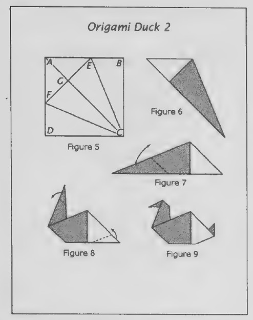 Transparency 3-4-3
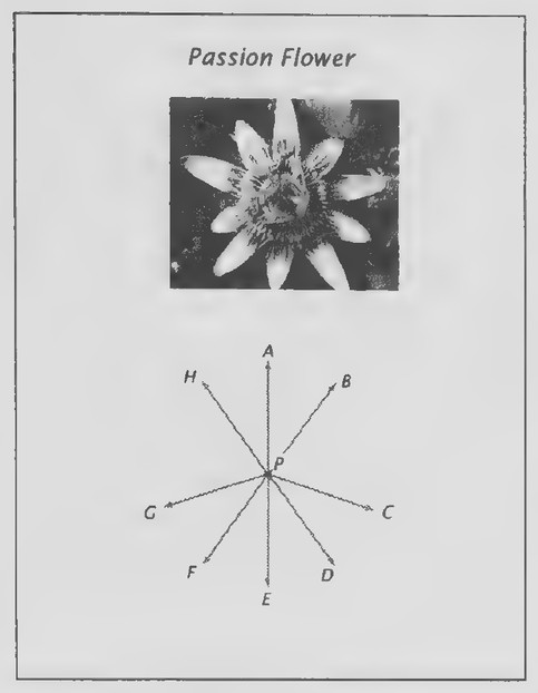 Transparency 3-4-4: Passion flower (Set II, Exs. 41-47)
 Transparency 3-5-1: Popular Mechanics stunt
visual fields of the eyes have relatively little overlap, and so the rabbit has a much more panoramic view of its surroundings. In general, predatory animals have better binocular vision, whereas nonpredatory animals have better panoramic vision. To which animal is your vision more comparable? (The cat.) How does the vision of a horse compare with your vision? (It is flatter but more panoramic.)
How do the angles of the visual fields of the individual eyes of a cat and rabbit compare? Have your students use their protractors to measure the angles. (They are the same, about 170°.) To find the centers of the visual fields of the eyes, we can bisect these angles. Use your protractor to do so. We could also have bisected the angles by using a straightedge and compass. Suppose you had neither these tools nor a protractor. Can you think of another way that you might accurately bisect the angles? (By folding the paper.) The rest of the lesson can now be developed as in the text. Alternate introduction Because the lesson on bisection is developed around paper folding, your students might enjoy being introduced to it by folding the origami duck pictured on page 101 of the text. I suggest using squares of paper measuring about 5 inches on a side. Illustrations for doing the folding are shown on Transparencies 3-4-2 and 3-4-3, and the directions, all from Peter Engel’s Folding the Universe (Vintage Books, 1989), are given below:
- Fold corner B over onto corner D. Unfold the
paper flat again (Figure 1).
- Fold sides BC and DC onto the fold AC (Fig-
ures 2 and 3).
- Fold corner A over onto the line where sides
BC and DC meet as shown by Figure 4.
- Unfold the paper flat again and label the
points indicated on Figure 5.
Before proceeding any further, ask the following questions. Which angles were bisected by the first fold? (The angles at A and C.) Which angles were bisected next? (∠DCA and ∠BCA.) Can you find any more angles that have been bisected? (∠FCE and the straight angles at G. We know that ∠FCE has been bisected because ∠DCA = ∠BCA
and so = DCA = + 2BCA; ∠EeA= = DCA and
1 ∠ECA = a oBCA; so ∠FCA = ∠ECA by substitu-
tion.) Can you find any line segments that have been bisected? (FE.) Introduce the word congruent in this discussion.
The remaining steps are a bit more complicated:
- Fold the paper so that it looks like figure 3
again.
- Refold along AC so that label A appears on
the outside rather than the inside (Figure 6).
- Turn the figure so that it is in the position
shown in Figure 7.
- Fold the lower left part inward as shown in
Figure 8 to form the neck.
9, Fold the top of the neck inward to form the
head and the lower right part inward to form
the tail (Figure 9).
The rest of the lesson can now be presented as in the text.
 Transparency 3-5-2: Fifteen squares (Set III)
 Transparency 3-6-1: German angles
 Transparency 3-6-2: German angle relations
Lesson 5: Complementary and Supplementary Angles
Lesson Outline
Terms: Complementary (complement), supplementary (supplement).
Theorem 3. Complements of the same angle are equal.
Theorem 4. Supplements of the same angle are equal.
Transparencies
- 3-5-1 Popular Mechanics stunt
- 3-5-2 Fifteen squares (Set III)
Introduction
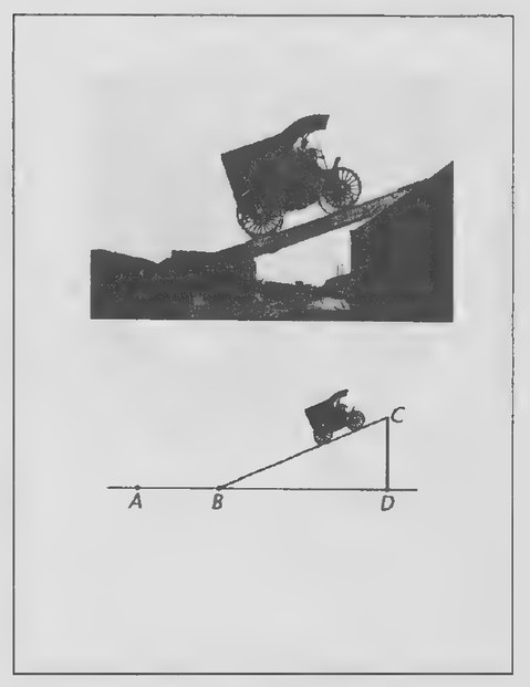
In the early days of automobiles, motorists frequently had to get out of their cars and push them when they came to a slight grade. The photograph on Transparency 3-5-1 is from a 1902 issue of Popular Mechanics magazine and shows a car being driven up a ramp to the top of a house. The purpose of the photograph was to demonstrate the power and grade-climbing ability of the car, both of which were unusual for the time. Modern cars are more powerful but also a lot heavier. It is hard to imagine such a stunt being carried out today!
The drawing below the photograph represents the ramp, the side of the house, and the ground. Guide your students in making a copy of it by doing the following:
- Draw a horizontal line to represent the
ground. Mark a point B on it to represent
the bottom of the ramp and a point D to
represent the base of the house.
- Use your protractor to draw a line to
represent the ramp, given that it rises 23°
with the ground.
- Use the protractor to draw a line at D to
represent the side of the house.
- Label the point C in which these two lines
intersect to represent the top of the ramp.
- Choose and label a point A on the ground
line as shown in the figure.
Ask your students to measure ∠C, the angle that the ramp makes with the side of the house. Can you think of a way to figure out the size of ∠C without measuring it? (By the Triangle Angle Sum Theorem: the sum of the angles of triangle BCD is 180°; ∠BCD = 90° and ∠CBD = 23°; so ∠C = 180° — 90° — 23° = 67°.) Can you tell the measure of ∠ABC without measuring it? (∠ABD is a straight angle; so ∠ABC = 180° - 23° = 157°.) So ∠CBD + ∠C = 90° and ∠CBD + ∠ABC = 180°.) These results lead naturally into a discussion of complementary and supplementary angles and the rest of the lesson.
Lesson 6: Linear Pairs and Vertical Angles
Lesson Outline
Terms: Opposite rays, linear pair, vertical angles.
Theorem 5. The angles in a linear pair are supplementary.
Theorem 6. Vertical angles are equal.
Transparencies
- 3-6-1 German angles
- 3-6-2 German angle relations
- 3-6-3 Hedge shears (Set II, Exs. 40-43)
- 3-6-4 Pinhole camera (Set II, Exs. 46 and 47)
- 3-6-5 Chinese proof (Set III)
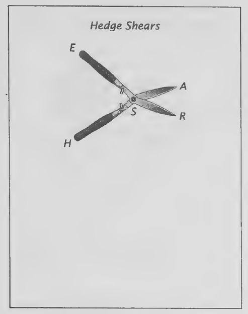 Transparency 3-6-3: Hedge shears (Set II, Exs. 40-43)
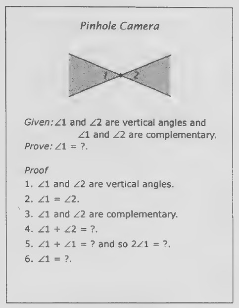 Transparency 3-6-4: Pinhole camera (Set II, Exs. 46 and 47)
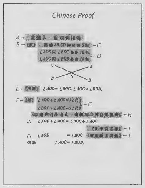 Transparency 3-6-5: Chinese proof (Set III)
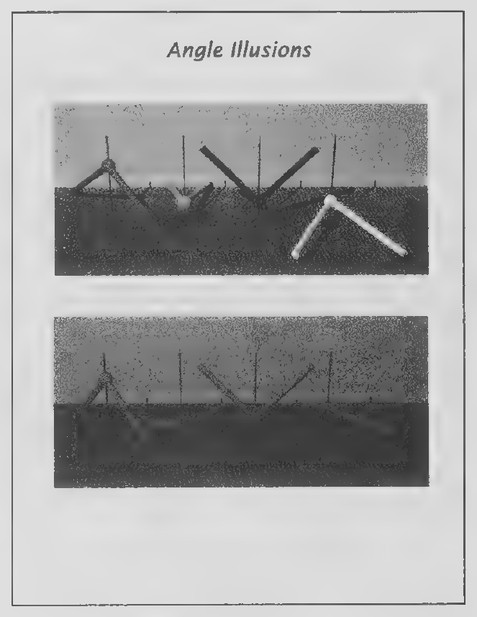 Transparency 3-7-1: Angle illusions
Introduction
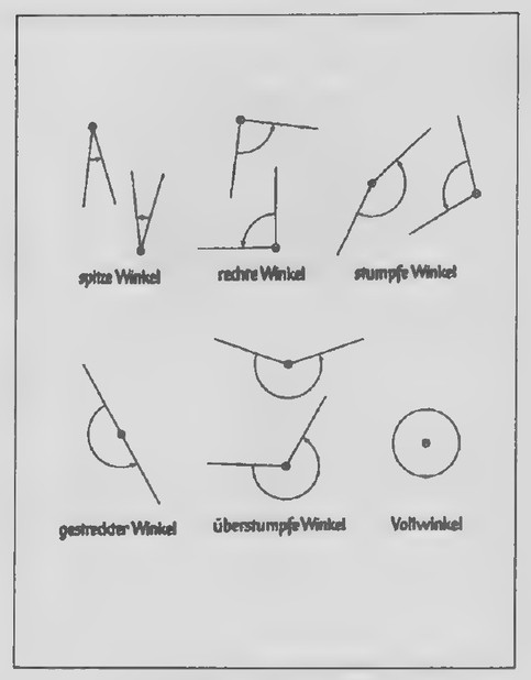
Transparencies 3-6-1 and 3-6-2 show some terms about angles from a German geometry book. The illustrations on the first transparency name angles according to their measures: Winkel means “angle”; spitze means “pointed” or “acute”; rechte, “right”; stumpfe, “blunt,” “stupid,” or “obtuse”; and gestreckter, “enlongated” or “straight.” The next term names a type of angle that we will not encounter until later: iiberstumpe in German means “beyond stupid” or “beyond obtuse.” Our term for it is “reflex.” The final term refers to the angle through which something turns in making one full revolution: Voll appropriately means “full.”
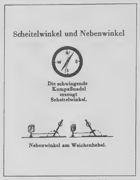
The terms on the second transparency refer to angle relations: Scheitel means “part,” as in the hair, and neben means “beside.” The caption of the first illustration states that the swinging compass needle produces “scheitelwinkel,” angles that we call vertical. The second illustration shows two positions of a railroad switch, and the caption states that “nebenwinkel,” angles that we called a linear pair, appear in a yield lever. With this introduction, the idea of opposite rays can be introduced, and the rest of the lesson can be developed as in the text.
Lesson 7: Perpendicular and Parallel Lines
Lesson Outline
Terms: Perpendicular, parallel.
Theorem 7. Perpendicular lines form four right angles.
Corollary to the definition of a right angle. All right angles are equal.
Theorem 8. If the angles in a linear pair are equal,
then their sides are perpendicular.
Transparencies
- 3-7-1 Angle illusions
- 3-7-2 A deceptive figure (Set II, Exs. 23-27)
Introduction
The photographs on Transparency 3-7-1 were created by scientists at Duke University and are from Al Seckel’s beautiful book titled The Great Book of Optical Illusions (Firefly Books, 2002). The first photograph shows models of four angles mounted on sticks. Which angle do you think is the largest and which angle do you think is the smallest? (All four angles are right angles!) As Seckel reports: “According to Duke University neuroscientists Dale Purvis,
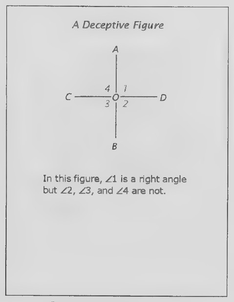 Transparency 3-7-2: A deceptive figure (Set II, Exs. 23-27)
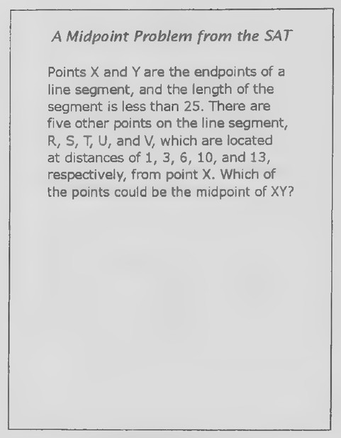 Transparency 3-R-1: A midpoint problem from the SAT
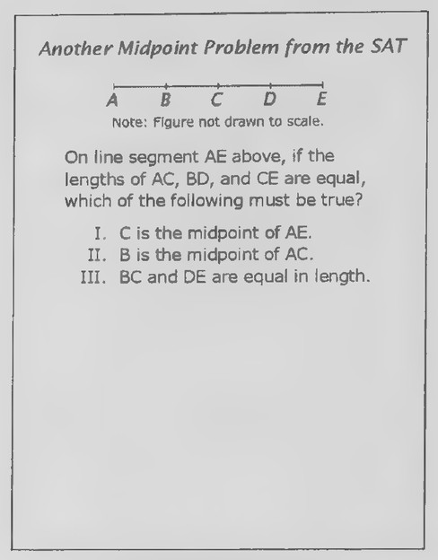 Transparency 3-R-2: Another midpoint problem from the SAT
ing to Duke University neuroscientists Dale Purvis, R. Beau Lotto, and Suragit Nundy, the orientation of the angle exerts a strong bias in the judgment of its extent, depending on the frequency of occurrence of particular angles at that orientation in our experience. Angles at the orientation of the red angle tend to be large and [those at the orientation of] the green angle tend to be small, so we overestimate the red as large and we underestimate the green.”
How do the angles in the lower photograph appear to compare in size? (Although they may appear to be right angles and hence equal, they actually differ considerably in size.)*
These questions lead directly into the definition of perpendicular lines and the rest of the new lesson.
Review of Chapter 3
Transparencies
- 3-R-1 A midpoint problem from the SAT
- 3-R-2 Another midpoint problem from the SAT
- 3-R-3 Chair design (Set II, Exs. 37-40)
- 3-R-4 The geometry of a pencil point
First day
Introduction
Transparencies 3-R-1 and 3-R-2 contain two problems that have appeared on SAT tests in the past.
“More on the topic of angle perception can be found in an article titled “Why We See What We Do” in the May-June 2002 issue of American Scientist and in the book of the same name by Dale Purves, Michael A. Wieder, and R. Beau Lotto (Sinauer, 2003).
Both are about midpoints. The first is a good exercise in indirect reasoning and the second, in direct reasoning.
Problem 1. (Suggest that your students draw a figure in which they assign the coordinate 0 to point X. The coordinates of R, S, T, U, and V are 1, 3, 6, 10, and 13, respectively, and the coordinate of Y is less than 25.) Point V cannot be the midpoint of XY, because, if it were, the coordinate of Y would be 26. Point T cannot be the midpoint of XY, because, if it were, the coordinate of Y would be 12; this contradicts the fact that V is on line segment XY. Points R and S are ruled out in the same way; so only U could be the midpoint of XY.
Problem 2. We are given that AC = BD = CE. It immediately follows that AC = CE, and so C is the midpoint of AE. If we imagine that segment BD was moved to the right along the line without changing its length, it is clear that B need not be the midpoint of AC. BC and DE must be equal in length, as the following proof establishes. BD = CE (given). BD = BC+ CD and CE = CD + DE (Betweenness of Points Theorem). So BC + CD = CD + DE (substitution) and BC = DE (subtraction).
Second day
Introduction
Part of the pencil sharpening that goes on in every classroom is due to worn-down pencil leads and part is due to broken pencil points. Many years ago, Don Cronquist, an engineer in California, noticed that almost all broken pencil points have the same size and shape. In analyzing why this should be, Cronquist made drawings similar to the ones on
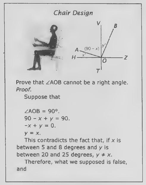 Transparency 3-R-3: Chair design (Set II, Exs. 37-40)
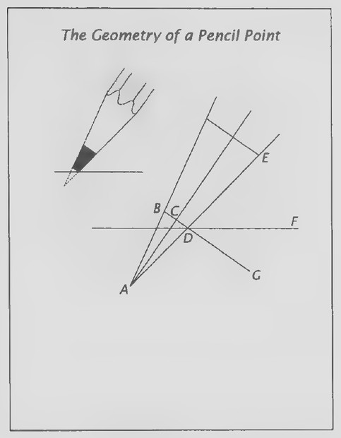 Transparency 3-R-4: The geometry of a pencil point
causing pencil points to break; we will look just at the angles in the figure. (This will be easier to do if you hand out duplicated copies of the transparency.) Although a scientist or engineer could use a protractor to measure all of the angles in a given figure, it is usually simpler to start with a few and use geometry to determine the rest. In the lettered figure, AC ∥ BG and AC bisects ∠BAD. Use your protractor to measure ∠BAD, the angle of the cone of the pencil lead, and ∠EDF, the angle of the lead with the paper. (∠BAD = 20°, ∠EDF = 45°.) Now put your protractor aside and see how many of the following angles you can figure out.
∠CAD. (10°, because AC bisects ∠BAD.)
∠ACD. (90°, because AC 1 BG.)
∠CDA. (80°, because it is the third angle in
△CAD. We have just found the measures of
the other two angles and so, from the
Triangle Angle Sum Theorem, we have
∠CDA = 180° — 10° - 90°.)
- What relation does ∠CDA have to ∠CAD?
(They are complementary.)
- ∠EDG. (80°, because ∠EDG and ∠CDA are
vertical angles. Vertical angles are equal.)
- ∠FDG. (35°. DE-DF-DG, and so ∠EDF +
∠FDG = ∠EDG; ∠EDF = 45° and ∠EDG =
80°.)
. ∠ADG. (100°, because ∠ADG and ∠EDG form a linear pair. The angles in a linear pair are supplementary.). ∠BDE. (100°, because ∠BDE and ∠ADG are vertical angles.)
*Don Cronquist’s study of broken pencil points was reported by Jearl Walker in his “Amateur Scientist” column in the February 1979 issue of Scientific American. Henry Petroski also includes it in chapter 3, “Pencil Points and Analysis,” of his book titled Invention by Design—How Engineers Get from Thought to Thing (Harvard University Press, 1996).
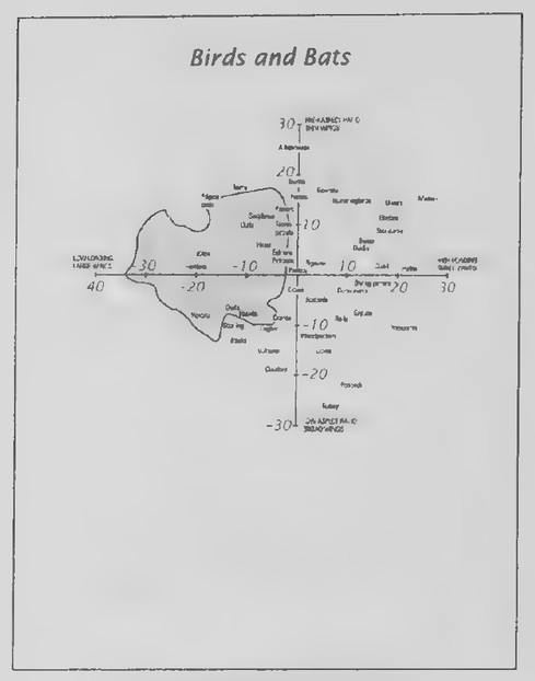 Transparency 4-1-3: Bird and bats (Set I, Exs. 16-22)
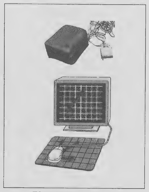 Transparency 4-1-1: Computer mouse
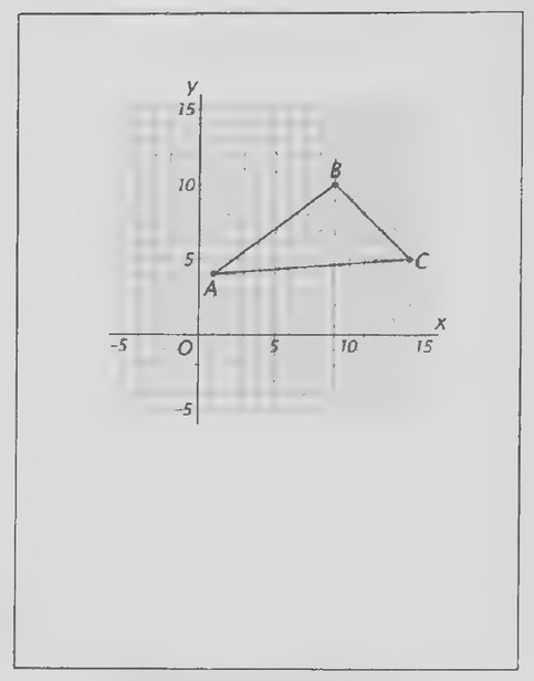 Transparency 4-1-2: Triangle and coordinate system